
Page 33 - machining_titanium_05_2019
P. 33
Face Milling
In face milling, starting feed per tooth fz is calculated by equation (7):
fz=fzo×1/sinχ ×Ks (7) MILLING TITANIUM
Here: fzo – basic feed per tooth (Table 18),
χ – cutting edge (entering) angle,
Ks – stability factor.
Face milling features considerable width of cut: normally ae=(0.6…0.8)×d. Therefore, for quick
estimation fzo may be set as the basic feed per tooth from Tables 15 and 16 that corresponds
ae/d=0.75. The appropriate values of fzo for indexable milling cutters are shown in Table 18.
Table 19 gives already calculated values of 1/sinχ for typical cutting edge angles of face mills.
Table 18 Basic Feed per Tooth fzo and Chip Thickness Data
for Indexable Face Milling
Fzo, mm/tooth (ipt), and hm and hmax, mm (in), for carbide grade of inserts*
Main grades Complementary grades
IC808 IC830 IC330
Parameters IC908 IC840 IC882 IC5820 IC380 IC928 IC328
0.095 0.095 0.11 0.095 0.078 0.11 0.11
Hm
(.0037) (.0037) (.0043) (.0037) (.0031) 0043) (.0043)
0.11 0.11 0.125 0.11 0.09 0.125 0.125
Hmax
(.0043) (.0043) (.0049) (.0043) (.0035) (.0049) (.0049)
0.11 0.11 0.125 0.11 0.09 0.125 0.125
Fzo
(.0043) (.0043) (.0049) (.0043) (.0035) (.0049) (.0049)
* The table values are given in metric units with their US customary equivalents in italic brackets:
fz in mm/tooth (ipt), hm and hmax in mm (in)
Table 19 Calculated Values Of (1/Sinχ) for Typical Cutting Edge Angles
Χ 90° 75° 65° 60° 45° 30°
1/sinχ 1 1.03 1.1 1.15 1.4 2
Cutting edge angle and lead angle are not synonyms!
The “cutting edge angle” is the angle between the main cutting edge of a milling cutter and
the plane containing the direction of feed motion. "Lead angle" (or “approach angle”) is the
angle complementary to the cutting edge angle, i.e. the sum of both these angles is 90°. For a
typical face milling cutter, the cutting angle is the angle between the cutting edge and the plane,
which the cutter generates. If this angle is 60°, then the lead angle will be 30°. The cutting edge
angle and the lead angle are equal only for 45° milling cutters. The term "lead angle" is more
commonly employed in the U.S., while "approach angle" is often used in Europe and Japan.
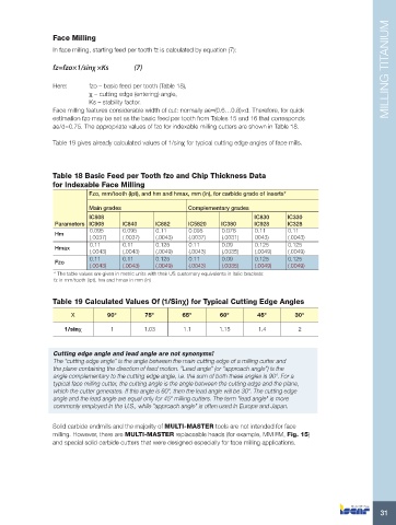
Solid carbide endmills and the majority of MULTI-MASTER tools are not intended for face
milling. However, there are MULTI-MASTER replaceable heads (for example, MM FM, Fig. 15)
and special solid carbide cutters that were designed especially for face milling applications.
31