
Page 42 - machining_titanium_05_2019
P. 42
MILLING TITANIUM Applications
The main operations performed by FF tools are rough milling pockets and cavities
(“pocketing”), pre-shaping complex surfaces (“profiling”) and plane faces (“facing”). Some
of the tools feature side plunge milling capabilities (“side plunging”). Milling pockets and
cavities are the most common cutting operations performed in producing titanium parts.
It is worth noting however, that fast feed face milling titanium is still not as
popular as steel. The reason is, again, heat. Thick chips, produced by an
FF tool, makes heat removal from the cutting zone more difficult.
Also, face mills generally feature relatively large diameters that increase the
contact of an insert with the machined material. This results in intensifying
the heat load on the cutting edge and shortening tool life.
By contrast, applying FF tools to pocketing enables decreasing the bending
force in high feed milling and therefore this method is recommended for rough
machining pockets and cavities in thin-walled and low-rigidity parts.
Fast Feed Facing
Initially the FF cutters were considered mainly as tools for productive rough milling of cavities and
punches in die and mold applications. The FF approach was later applied to face milling.
Fast feed face milling ( “fast feed facing” or, simply, “triple F”) with the use of indexable cutters,
opened another application field for FF tools.
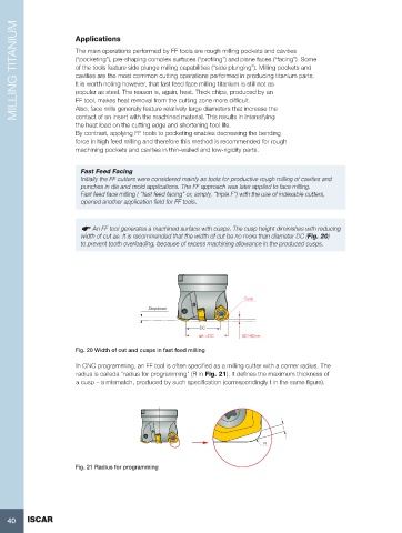
An FF tool generates a machined surface with cusps. The cusp height diminishes with reducing
width of cut ae. It is recommended that the width of cut be no more than diameter DC (Fig. 20)
to prevent tooth overloading, because of excess machining allowance in the produced cusps.
Cusp
Stepdown
DC
ae >DC ap>apmax
Fig. 20 Width of cut and cusps in fast feed milling
In CNC programming, an FF tool is often specified as a milling cutter with a corner radius. The
radius is calleda "radius for programming" (R in Fig. 21). It defines the maximum thickness of
a cusp – a mismatch, produced by such specification (correspondingly t in the same figure).
t
R
Fig. 21 Radius for programming
40 ISCAR