
Page 46 - machining_titanium_05_2019
P. 46
MILLING TITANIUM n a n n
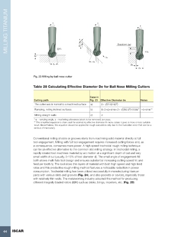
ap + V F α Stepdown (ap) V F
V F
de
de ae
de
Fig. 23 Milling by ball nose cutter
Table 28 Calculating Effective Diameter De for Ball Nose Milling Cutters
Case in
Cutting path Fig. 23 Effective Diameter de Notes
2
The cutter axis is normal to a machined surface a) 2× √(d×ap-ap )
2
Ramping, milling inclined surfaces b) (b-2×a)×sinαr+2× √(dxa-a )×cosαr* ≈d×sinαr**
Milling straight walls c) d
* αr - ramping angle, a - machining allowance (stock to be removed) per pass.
** The simplified equation is often used for estimating effective diameter. In many cases it gives a more or less suitable
result. Nevertheless, this equation should be applied for rough calculation only due to the truncation error that can be a
serious of inaccuracy.
Conventional milling of slots or grooves starts from machining solid material directly at full
tool engagement. Milling with full tool engagement requires increased cutting forces and, as
a consequence, consumes more power. A high speed trochoidal rough milling technique
can be an effective alternative to the common slot milling strategy. In trochoidal milling, a
rapidly rotated tool machines material by arc motion at a significant depth of cut and very
small width of cut (usually, 5-15% of tool diameter d). The small angle of engagement AE
both allows multi-flute tool design and ensures substantial increasing cutting speed Vc and
feed per tooth fz. The tool slices thin layers of material with both high speed and high feed
rates and this productive rough milling method features a noticeable reduction in power
consumption. Trochoidal milling has been utilized successfully in manufacturing titanium
parts with various slots and grooves (Fig. 24), and also pockets or cavities¸ especially those
with relatively thin walls. The metalworking industry adopted this method for producing
different integrally bladed rotors (IBR) such as blisks, blings, impellers, etc. (Fig. 25)
44 ISCAR