Page 41 - NEW PRODUCT CATALOG 2022 INCH
P. 41

OAH      OAW A-A     A-A
                                                                                     LF                               HTPRM
TGTBY-JHP                                                                       OAL CUTDIA
Y-Axis Intermediate Prismatic                                                                                                                                               PSI
Holders for Square JHP                                                                            HF
Adapters on Multi-Task Machines                                                                                       LB
for Parting and Grooving                                                                                                     TGTBY R32-D82R-JHP with TGAQ Shown

Designation                      OAH HF OAW LF                                                          LB  CUTDIA    OAL(1)                             OAL_2(2)           HTPRM

TGTBY R/L32-D82R-JHP             2.591  2.591             .630 5.906 2.441 3.228 6.024 6.157 1.260

TGTBY R/L32-D82L-JHP             2.591  2.591             .630 5.906 2.441 3.228 6.024 6.157 1.260

• Can be used also for X-axis (multi-task machines) - location pin should be removed • The tool types shown are currently unavailable in the USA, Canada, China, Japan and Korea.

(1) Overall length with TGAQ adapter

(2) Overall length with DGAQ adapter

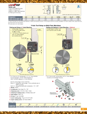
                                             Y-Axis Tool Setup on Multi-Task Machines

Parting and Setup in Y-Axis Direction                                           Parting and Setup in X-Axis Direction - Optional

   Cutting edge is located:                               TGTBY                 Cutting edge is located 1.08”                                            TGTBY
1. 1.21” from machine center                                                    from machine center line ( )

   line ( ) in Y-Axis                                                                                *1.08” REF
2. .118” from for TGAQ adapter and

   .252” for DGAQ adapter
   (see sketches below)

                *1.21” REF

             X

                                        Feed (in Y axis)             *.118”                                                            Feed (in X axis)

                                                                      REF

Y

                                                      Machine Probe

                                      n

                        X        Option 1Option 2                                                           Y                                    Y
                                                                                                                                 n
             For TGAQ                    For DGAQ                                                           Correct
              Adapters                    Adapters                                                          Position          Correct
                                                                                                                      X Position

             .118” REF                  .252” REF

                                       Setup cutting edge level on center line                                     Setup cutting edge level on center line

  * For Y-Axis cut off, compensate 1.21” in Y Axis direction                    * For X-Axis cut off, compensate 1.08” in Y-Axis direction.

     and compensate .118” for TGAQ adapters or                                     Location pin should be removed.
     .252” for DGAQ adapters in X-Axis direction.
                                                                                                      1
     Set the cutting edge on the center line:                                                                                                                            8
     Option 1 - Gauge the cutting edge - this is preferable due to
                                                                                                      3                             6
                   better accuracy                                                                                    53
     Option 2 - Gauge the blade and compensate .118 / .252”                                           2
  1. Block: TGTBY                                                               Remove Pin for
  2. Locating pin: Side thrust Pin .118”                                        X-Axis Machinning
  3. Clamping screw : SR M4x10 ISO 14580
  4. Clamping & sealing screw : SR M4x9-Seal-JHP                                                    4
  5. Seal washer: CSW 1/8’’
  6. O-ring: O-ring 10x2 NBR                                                                                                                             7
  7. Lower sealing plug : Plug G1/8-6.5 TL360
  8. Upper sealing screw : SR M3x4-DIN913

Spare Parts

Designation
TGTBY-JHP SR ISO 14580 M4X10 SR M4X9-SEAL-JHP OR 16X2 NBR JHP COPPER SEAL 1/8" BLD T20/S7 SW6-SD PLG G1/8 TL360 HW 5.0 SIDE THRUST PIN 3mm

                                                                                                                                                                                   39
   36   37   38   39   40   41   42   43   44   45   46