
Page 37 - TURNING CATALOG p635-848
P. 37
±0.025 17.7 Ref.(a) IC08
IC908
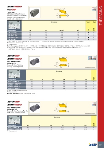
TIP-P-NPT 60° CW
NPT (National Pipe Threads) RE THREADING
Precision Ground Double-Ended
External Full Profile Threading Dimensions
Inserts with a Chipformer
NUT Tough 1 Hard
30° 30°
90° 1°47' SCREW
Designation CW RE RETOL(1) TPI(2)
0.05 0.030 27.0 • •
TIP 2P27-NPT 2.40 0.07 0.030 18.0 • •
TIP 2P18-NPT 2.40 0.09 0.030 14.0 •
TIP 2P14-NPT 2.40 0.10 0.030 11.5 • •
TIP 4P11.5-NPT 4.00 0.13 0.030 8.0 • •
TIP 4P8-NPT 4.00
• (a) TIP inserts are 1.6 mm longer than GIP in the same pocket • Toolholder seat needs to be modified according to insert profile to ensure clearance
(1) Corner radius tolerance (+/-)
(2) Threads per inch
For tools, see pages: C#-GHDR/L (274) • CGHN-D (283) • CGHN-DG (283) • CGHN-S (282) • CGPAD (281) • CGPAD-JHP (282) • GHDR/L (short pocket) (275)
• GHDR/L-JHP (short pocket) (276) • GHDR/L-JHP-MC (short pocket) (277) • GHGR/L (278) • GHMPR/L (273) • GHMR/L (273) • GHSR/L (373)
• GHSR/L-JHP-SL (374) • NQCH-GHSR/L-JHP (374)
NPT THREADING S INSL BW
FLDC-V-75 PDX 3˚
Double-Ended, Precision, 60˚
Flat Top Threading Inserts
Right-hand shown
NUT Dimensions
INSL
30° 30°
22.60 •
90° 1°47' SCREW 22.60 • IC908
22.60 •
Designation TPI(1) IPF PDX BW S 22.60 •
22.60 •
FLDC-3-8VR/L75 8.0 3/4 2.50 4.95 8.74
FLDC-3-115VR/L75 11.5 3/4
14.0 3/4 3.70 4.95 8.74
FLDC-3-14VR/L-75 18.0 3/4
27.0 3/4 3.80 4.95 8.74
FLDC-3-18VR/L-75
FLDC-3-27VR/L-75 3.90 4.95 8.74
4.10 4.95 8.74
• DMIN according to related boring bar
(1) Threads per inch
For tools, see pages: FLASR/L (708) • FLSR/L (708)
NPT THREADING S INSL
FLDC-NPT-E PDX BW
Double-Ended, Precision, Flat Top 60˚
Multi-Tooth Threading Inserts
Right-hand shown
NUT Dimensions
30° 30°
90° 1°47' SCREW IC908
Designation TPI(1) IPF PDX BW S INSL
3/4 1.50 6.35 8.74 22.60 •
FLDC-3-8NPT 2E 8.0 8.74 22.60 •
FLDC-3-11.5NPT-2E 11.5 3/4 1.20 6.35
(1) Threads per inch
671