
Page 64 - MILLING CATALOG p549-788
P. 64
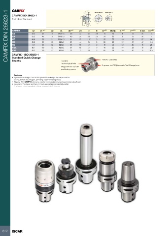
CAMFIX DIN 26623-1                                                                                           l8       C      Section view A-A  Section view C-C
                                                                                                          l7             A                                 2e

                    CAMFIX ISO 26623-1                                                                    d4
                    Toolholder Standard
                                                                 d2 d1                                                                                                        Dm
                                                                                                                             b2
                                                                                                          d5
                                                                                                                 l1       A
                                                                                                                 l11  l6

                                                                                                              l2       l3
                                                                                                                      C

                    CAMFIX  b2 d1 ±0.1     d2 d4 d5 ±0.1         Dm e                                                        l1 l2 ±0.1 l3 min                                    l6 ±0.15  l7 ±0.15  l8 min  l11 ±0.1
                            28.3 32                              22 0.7                                                                                                              6        13        25       8
                    C3      35.3 40        15 M12x1.5  3.6       28 0.9                                                      2.5 19            15                                    8        15        30       8
                    C4      44.4 50                              35 1.12                                                                                                            10        20        37      14
                    C5      55.8 63        18 M14x1.5  4.6       44 1.4                                                      2.5 24            20                                   12        27        47     15.5
                    C6      71.1 80                              55 2                                                                                                               12        28        48      25
                    C8      88.7 100       21 M16x1.5  6.1       55 2                                                        3 30 20                                                16        28        48      25
                    C8X     88.3 100                             72 2.8                                                                                                             16        40        70     26.5
                    C10                    28 M20x2    8.1                                                                   3 38 22

                                           32 M20x2    9.1                                                                   3 48 30

                                           32 M20x2    9.1                                                                   3 48 32

                                           43 M20x2    12                                                                    3 60 36

                    CAMFIX - ISO 26623-1   Coolant                                                                           Hole for Data Chip
                    Standard Quick Change  technological hole                                                                V-groove for ATC (Automatic Tool Change) arm
                    Shanks
                                           Magazine and spindle
                                           positioning groove

                       Features
                    • Symmetrical design: Due to the symmetrical design, the torque load is

                       distributed on the polygon, providing a self-centering effect.
                    • Rigidity: The CAMFIX clamping mechanism is extremely rigid against bending forces.
                    • Accuracy: The taper and face contact ensure high repeatability within

                       2 microns, when operated with an automatic tool changer.

612 ISCAR