
Page 43 - HOLE_MAKING_CATALOG_INCH_2022_P237-P372
P. 43
USER GUIDE
Technical Information -
Cartridge Style Drill Head Diameter Settings
The drill head diameter is set and inspected with a master insert in our final inspection. However, the inserts in the market
have a tolerance fluctuation so each time you index the insert, the diameter must be adjusted as per the following method.
Note: When a corner change is made on the insert, it must be adjusted to the correct
size or damage can be caused to the head body or workpiece material.
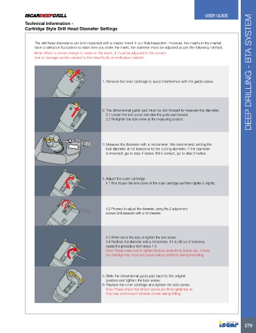
1. Remove the inner cartridge to avoid interference with the guide screw. DEEP DRILLING - BTA SYSTEM
2. The dimensional guide pad must be slid forward to measure the diameter.
2.1 Loosen the lock screw and slide the guide pad forward.
2.2 Re-tighten the lock screw at the measuring position.
3. Measure the diameter with a micrometer. We recommend setting the
tool diameter at h8 tolerance to the cutting diameter. If the diameter
is incorrect, go to step 4 below. If it’s correct, go to step 5 below.
4. Adjust the outer cartridge
4.1 First loosen the lock screw of the outer cartridge and then tighten it slightly.
4.2 Proceed to adjust the diameter, using the 2 adjustment
screws and measure with a micrometer.
4.3 When set to the size, re-tighten the lock screw.
4.4 Recheck the diameter with a micrometer. If it is still out of tolerance,
repeat the procedure from steps 1-4.
Note: Please make sure to tighten the lock screw firmly before use. If loose,
the cartridge may move and cause serious problems during machining.
5. Slide the dimensional guide pad back to the original
position and tighten the lock screw.
6. Replace the inner cartridge and tighten the lock screw.
Note: Please check that all lock screws are firmly tightened, as
they may come loose if vibration occurs during drilling.
279