
Page 114 - HOLE_MAKING_CATALOG_INCH_2022_P447-P626
P. 114
ITS BORE Fine Boring Head BHFI 16-50 USER GUIDE
Operating Instructions
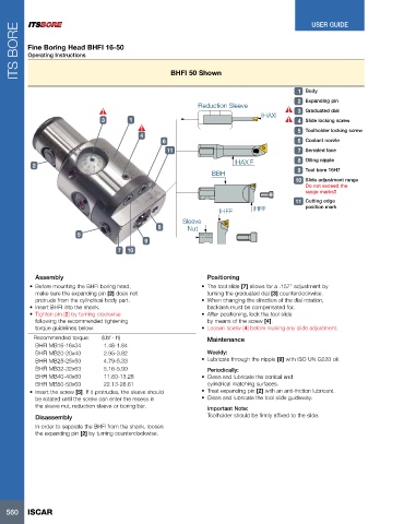
BHFI 50 Shown
1 Body
2 Expanding pin
Reduction Sleeve
IHAXF 3 Graduated dial
3 1 4 Slide locking screw
5 Toolholder locking screw
4
6 6 Coolant nozzle
11 7 Serrated face
IHAX F 8 Oiling nipple
2
BBH 9 Tool bore 16H7
10 Slide adjustment range
Do not exceed the
range marks!!
11 Cutting edge
IHFF IHFF position mark
Sleeve
8 Nut
5
9
7 10
Assembly Positioning
• Before mounting the BHFI boring head, • The tool slide [7] allows for a .157” adjustment by
make sure the expanding pin [2] does not turning the graduated dial [3] counterclockwise.
protrude from the cylindrical body part. • When changing the direction of the dial rotation,
• Insert BHFI into the shank. backlash must be compensated for.
• Tighten pin [2] by turning clockwise • After positioning, lock the tool slide
following the recommended tightening by means of the screw [4].
torque guidelines below: • Loosen screw [4] before making any slide adjustment.
Recommended torque: (Lbf ∙ ft) Maintenance
BHFI MB16-16x34 1.48-1.84
BHFI MB20-20x40 2.95-3.82 Weekly:
BHFI MB25-25x50 4.79-5.33 • Lubricate through the nipple [8] with ISO UN G220 oil.
BHFI MB32-32x63 5.16-5.90 Periodically:
BHFI MB40-40x80 11.80-13.28 • Clean and lubricate the conical and
BHFI MB50-50x60 22.13-28.81 cylindrical matching surfaces.
• Insert the screw [5]. If it protrudes, the sleeve should • Treat expanding pin [2] with an anti-friction lubricant.
be rotated until the screw can enter the recess in • Clean and lubricate the tool slide guideway.
the sleeve nut, reduction sleeve or boring bar. Important Note:
Disassembly Toolholder should be firmly affixed to the slide.
In order to separate the BHFI from the shank, loosen
the expanding pin [2] by turning counterclockwise.
560 ISCAR