
Page 122 - HOLE MAKING CATALOG p185-310
P. 122
GUNDRILLS USER GUIDE
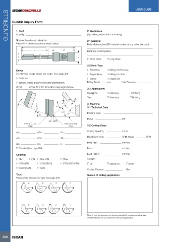
bF1Gundrill Inquiry Form
1. Tool 2. Workpiece
Quantity (If possible, please attach a drawing)
Nominal diameter and tolerance LA 2.1 Material
Please fill in dimensions on the sketch below. Material description (DIN material number or any other standard):
L Hardness and Properties:
Ls
D d o Short Chips o Long Chips
Driver 2.2 Hole Type o Drilling into Pre-hole
For standard drivers please use codes from page 301
o Blind Hole o Drilling into Solid
o Code No. o Angled Entry
o Special, please attach sketch and specifications. o Boring o Angled Exit
Grind: o special (fill in the dimensions and angles below). Drilling Depth mm Hole Tolerance
2.3 Application:
Workpiece: o Stationary o Rotating
Tool: o Stationary o Rotating
γ αF1 3. Machine kW
α1 3.1 Technical Data
α2
ψ2 ψ1 Machine Type.
α3
Inter nal Cuttnig Power
Edge as
exter nal Cuttnig 3.2 Cutting Data:
Edge
α1= αF1= Ψ1= Cutting Speed Vc m/min
α2= bF1= Ψ2=
α3= as= γ= Revolutions Nmin RPM, Nmax RPM
o Standard (see page 299)
Feed Fmin mm/rev,
Fmax mm/rev
Coating: Feed Rate VF mm/min
Coolant:
o TiN o TiCN o TiN+TiCN o Other o Oil
o IC508 (TiCN+TiN)
o IC208 (TiN) o IC308 (TiCN) o Soluble Oil o Other
o IC908 (TiAlN) o TiAIN Coolant Pressure Bar
Type: Sketch of drilling application
Please circle the required type. See page 300.
D
A BC
E GH I
Note: It may be necessary to change several of the parameters that you
indicated based on our experience with your application.
306 ISCAR