
Page 119 - HOLE MAKING CATALOG p185-310
P. 119
USER GUIDE GUNDRILLS
Standard Gundrill Length Calculations
H Example
D Drilling of a ø10x500 depth hole on a gundrill machine with
ø25x70 mm driver code No. 57 (See page 302)
NW Ls BF LA D=10 W=500 LA=70 B=250 (or per experience)
L=N+W+B+F+LA
L L=(35-10)+500+250+13+70=858 (OAL)
Ls=N+W+B=770 (flute length)
Standard Gundrill Carbide Head Length Ordering Code
For example:
H D and Ls are available as standard
STGD-10000-0858-57-IC08
D Head Length
Diameter Range 20
D= Cutting diameter 2.50-3.80 23
H= Carbide length 3.80-4.05 25
N= Regrinding area = H-D 4.05-5.05 30
W= Hole depth 5.05-6.55 35
B= Chip evacuation area = For typical 6.55-11.05 40
45
gundrill machines, 250 mm 11.05-18.35 50
= For machining centers, 2xD (minimum 15 mm) 18.35-21.35 55
F= 10 mm. 21.35-23.35 65
LA = Driver length 23.35-26.35
LS = Flute length 26.35-32.00
L= Overall length
Note: regrindable length=H-D
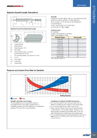
Pressure and Coolant Flow Rate for Gundrills
Bar L/min
120 L/D>100 Q 120
110 L/D<100 110
100 100
90 P L/D>100 90
L/D<100 80
80 70
70 60
60 50
50 40
40 30
30 20
20 10
10
Ø 2 4 6 8 10 12 14 16 18 20 22 24 26 28 30 32 40 mm
Drilling Diameter
Q l/min P bar
Gundrill Lubrication and Cooling Guidelines for Optimal Gundrill Performance
The best performance is obtained by using oil. • It is recommended to use a strong coolant flow for
On equipment that uses water-soluble fluids (i.e.
machining centers and CNC machines), a concentration efficient chip flushing and cooling of the cutting edge
between 10% and 15% is recommended. • It is recommended to use a filter under 20 µm
• Note: Improper filtration may result in interrupted flow
of lubricating oil. This creates a sticky surface on the
bearing pads and leads to premature wear of the tool
and overloading the coolant pump and spindle seals
• The coolant temperature should be between 20 and 22º C.
Note: Above 50º C the viscosity of the coolant is reduced by 50% and
becomes ineffective.
303