Page 41 - TURNING CATALOG p255-458
P. 41

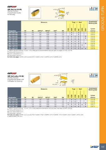
GIP (flat top W<M)                                            ±0.025      15.3 Ref.                         IC830
Flat Top Precision                                                                                                 IC808
Double-Ended Inserts                                                 7°                                     5             IC908
for Grooving                                                  CW                                                                  IC20
                                                                                                                                         IC20N
                                                              RE BW                                                                              IC807
                                                                                CDX
                                                                                                                                        GROOVE-TURN
                                           Dimensions                                                                 Tough 1  Hard                     Recommended
                                                                                                                                                        Machining Data

Designation                        CW  RE  CWTOL(1) RETOL(2)  CDX(3)                             BW            ••                                       f groove

GIP 0.50-0.00                      0.50 0.00 0.02 0.030 1.00 2.20                                              ••                                       (mm/rev)
GIP 0.80-0.00                                                                                                                                           0.02-0.04
GIP 1.04-0.00                      0.80 0.00 0.02 0.030 1.60 2.20                                                                     •                 0.02-0.04
GIP 1.20-0.00                      1.04 0.00 0.02 0.030 2.00 2.20 • • • •                                                                               0.02-0.05
GIP 1.40-0.00                      1.20 0.00 0.02 0.030 2.00 2.20 • • • •                                                             •                 0.03-0.05
GIP 1.47-0.00                      1.40 0.00 0.02 0.030 2.00 2.20 • • • •                                                                               0.03-0.06
GIP 1.57-0.15                      1.47 0.00 0.02 0.030 2.50 2.20 • • • •                                                                               0.03-0.06
GIP 1.70-0.10                      1.57 0.15 0.02 0.030 2.70 2.20 • • • •                                                             •                 0.04-0.06
GIP 1.78-0.18                      1.70 0.10 0.02 0.030 3.00 2.20 • • • • •                                                                             0.04-0.07
GIP 1.96-0.15                      1.78 0.18 0.02 0.030 3.00 2.20 • • • •                                                                               0.04-0.07
                                   1.96 0.15 0.02 0.030 3.00 2.20 • • • • • •                                                                           0.04-0.08

• DMIN for internal machining = 70 mm • For cutting speed recommendations and user guide, see pages 419-428, 432-436

(1) Cutting width tolerance (+/-)

(2) Corner radius tolerance (+/-)

(3) Cutting depth maximum

For tools, see pages: GHDR/L (short pocket) (275) • GHGR/L (278) • GHMPR/L (273) • GHMR/L (273)

                                                                                                 15.3 Ref.

GIP (full radius W<M)                                         ±0.025
Flat Top Precision
Double-Ended Inserts with                                                 7°
Full Radius for Grooving
                                                                                                                        5
                                                                      CW                           BW
                                                              RE=CW/2                            CDX                  Tough 1  Hard

                                           Dimensions                                                                                                   Recommended
                                                                                                                                                        Machining Data

Designation                        CW  RE  CWTOL(1) RETOL(2)  CDX(3)                             BW         IC830                                       f groove
                                                                                                                   IC808
GIP 1.00-0.50                                                                                                             IC908                         (mm/rev)
GIP 1.40-0.70                                                                                                                     IC20                  0.03-0.06
GIP 1.57-0.79                                                                                                                            IC806          0.04-0.07
GIP 2.00-1.00                                                                                                                                    IC807  0.04-0.08
GIP 2.39-1.20                                                                                                                                           0.05-0.11
                                   1.00 0.50 0.02 0.050 2.00 2.20                                              ••                     •                 0.06-0.12
                                                                                                               ••                     •
                                   1.40 0.70 0.02 0.050 2.00 2.20                                                                     •
                                   1.57 0.79 0.02 0.050 2.70 2.20 • • • •                                                             •
                                   2.00 1.00 0.02 0.050 3.00 2.20 • • • • •
                                   2.39 1.20 0.02 0.050 4.70 2.40                                              •••

• DMIN for internal machining = 70 mm • For cutting speed recommendations and user guide, see pages 419-428, 432-436

(1) Cutting width tolerance (+/-)

(2) Corner radius tolerance (+/-)

(3) Cutting depth maximum

For tools, see pages: GHDR/L (short pocket) (275) • GHGR/L (278) • GHMPR/L (273) • GHMR/L (273) • GHSR/L (373) • GHSR/L-JHP-SL (374)

• NQCH-GHSR/L-JHP (374)

                                                                                                                                                                        295
   36   37   38   39   40   41   42   43   44   45   46