
Page 112 - HOLE_MAKING_CATALOG_INCH_2022_P1-P186
P. 112
USER GUIDE
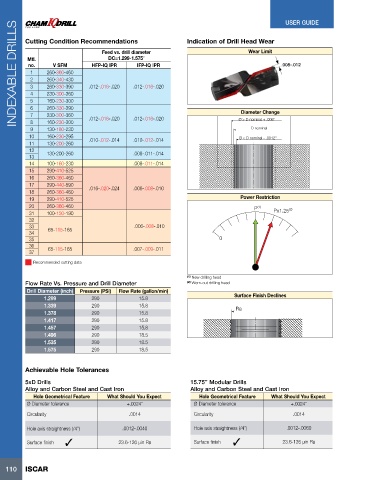
INDEXABLE DRILLS Cutting Condition Recommendations IFP-IQ IPR Indication of Drill Head Wear .008-.012
Wear Limit
Feed vs. drill diameter
DC=1.299-1.575”
Mtl.
V SFM
no.
HFP-IQ IPR
260-360-460
1
260-340-430
2
3
.012-.016-.020
260-330-390
.012-.016-.020
230-300-360
4
5
160-230-300
6
Diameter Change
7
230-300-360
8
160-230-300
D nominal
9 260-330-390 .012-.016-.020 .012-.016-.020 Ø > D nominal + .006"
130-180-230
10 160-230-295 .010-.012-.014 .010-.012-.014 Ø < D nominal - .0012"
11 130-200-260
12 130-200-260 .008-.011-.014
13
14 100-160-230 .008-.011-.014
15 290-410-525
16 260-360-460
17 290-440-590
18 260-360-460 .016-.020-.024 .006-.008-.010
19 290-410-525 Power Restriction
20 260-360-460 P (1) (2)
31 100-150-190 Px1.25
32
33 .006-.008-.010
34 65-115-165
35 0
36
37 65-115-165 .007-.009-.011
Recommended cutting data
(1) New drilling head
Flow Rate Vs. Pressure and Drill Diameter (2) Worn-out drilling head
Drill Diameter (inch) Pressure (PSI) Flow Rate (gallon/min)
1.299 290 15.8 Surface Finish Declines
1.339 290 15.8 Ra
1.378 290 15.8
1.417 290 15.8
1.457 290 15.8
1.496 290 18.5
1.535 290 18.5
1.575 290 18.5
Achievable Hole Tolerances
5xD Drills 15.75” Modular Drills
Alloy and Carbon Steel and Cast Iron Alloy and Carbon Steel and Cast Iron
Hole Geometrical Feature What Should You Expect Hole Geometrical Feature What Should You Expect
Ø Diameter tolerance +.0024” Ø Diameter tolerance +.0024”
Circularity .0014 Circularity .0014
Hole axis straightness (/4”) .0012-.0040 Hole axis straightness (/4”) .0012-.0060
Surface finish 23.6-126 µin Ra Surface finish 23.6-126 µin Ra
110 ISCAR