
Page 43 - HOLE_MAKING_CATALOG_INCH_2022_P187-P236
P. 43
USER GUIDE
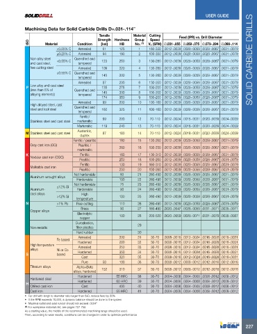
Machining Data for Solid Carbide Drills D=.031-.114”
Tensile Material Cutting Feed (IPR) vs. Drill Diameter
Strength Hardness Group Speed
ISO Material Condition [ksi] HB No. (1) Vc (SFM) Ø.031-.055 Ø.059-.075 Ø.079-.094 Ø.098-.114
<0.25% C Annealed 61 125 1 160-330 .0012-.0039 .0020-.0059 .0028-.0067 .0031-.0079
≥0.25% C Annealed 94 190 2 130-330 .0012-.0039 .0020-.0059 .0028-.0067 .0031-.0079
Non-alloy steel <0.55% C Quenched and 123 250 3 130-280 .0012-.0039 .0020-.0059 .0028-.0067 .0031-.0079 SOLID CARBIDE DRILLS
and cast steel, tempered
free cutting steel Annealed 109 220 4 130-280 .0012-.0039 .0020-.0059 .0028-.0067 .0031-.0079
≥0.55% C Quenched and 145 300 5 130-280 .0012-.0039 .0020-.0059 .0028-.0067 .0031-.0079
tempered
Annealed 87 200 6 130-250 .0012-.0039 .0020-.0059 .0028-.0067 .0031-.0079
Low alloy and cast steel
P 135 275 7 130-200 .0012-.0039 .0020-.0059 .0028-.0067 .0031-.0079
(less than 5% of Quenched and
alloying elements) tempered 145 300 8 130-200 .0012-.0039 .0020-.0059 .0028-.0067 .0031-.0079
174 350 9 130-200 .0012-.0039 .0020-.0059 .0028-.0067 .0031-.0079
Annealed 99 200 10 100-160 .0012-.0039 .0020-.0059 .0028-.0067 .0031-.0079
High alloyed steel, cast
steel and tool steel Quenched and 160 325 11 100-160 .0012-.0039 .0020-.0059 .0028-.0067 .0031-.0079
tempered
Ferritic/ 99 200 12 70-110 .0012-.0024 .0016-.0031 .0020-.0039 .0024-.0039
Stainless steel and cast steel martensitic
Martensitic 119 240 13 70-110 .0012-.0024 .0016-.0031 .0020-.0039 .0024-.0039
Austenitic,
M Stainless steel and cast steel 87 180 14 70-110 .0012-.0024 .0016-.0031 .0020-.0039 .0024-.0039
duplex
Ferritic / pearlitic 180 15 130-260 .0012-.0039 .0020-.0059 .0028-.0067 .0031-.0079
Gray cast iron (GG) Pearlitic / 260 16 130-230 .0012-.0039 .0020-.0059 .0028-.0067 .0031-.0079
martensitic
K Ferritic 160 17 130-310 .0012-.0039 .0020-.0059 .0028-.0067 .0031-.0079
Nodular cast iron (GGG)
Pearlitic 250 18 130-260 .0012-.0039 .0020-.0059 .0028-.0067 .0031-.0079
Ferritic 130 19 160-310 .0012-.0039 .0020-.0059 .0028-.0067 .0031-.0079
Malleable cast iron
Pearlitic 230 20 130-260 .0012-.0039 .0020-.0059 .0028-.0067 .0031-.0079
Not hardenable 60 21 260-490 .0012-.0039 .0020-.0059 .0028-.0067 .0031-.0079
Aluminum-wrought alloys
Hardenable 100 22 260-490 .0012-.0039 .0020-.0059 .0028-.0067 .0031-.0079
Not hardenable 75 23 260-490 .0012-.0039 .0020-.0059 .0028-.0067 .0031-.0079
≤12% Si
Aluminum- Hardenable 90 24 260-490 .0012-.0039 .0020-.0059 .0028-.0067 .0031-.0079
cast alloys High
>12% Si 130 25 260-490 .0012-.0039 .0020-.0059 .0028-.0067 .0031-.0079
temperature
N >1% Pb Free cutting 110 26 260-490 .0012-.0039 .0020-.0059 .0028-.0067 .0031-.0079
Brass 90 27 160-490 .0020-.0047 .0028-.0059 .0031-.0071 .0035-.0071
Copper alloys
Electrolytic 100 28 200-520 .0020-.0059 .0028-.0071 .0031-.0079 .0035-.0087
copper
Duroplastics,
Non metallic fiber plastics 29
Hard rubber 30
Annealed 200 31 30-70 .0008-.0016 .0012-.0024 .0016-.0028 .0016-.0031
Fe based
High temperature Hardened 280 32 30-70 .0008-.0016 .0012-.0024 .0016-.0028 .0016-.0031
alloys Ni or Co Annealed 250 33 30-70 .0008-.0016 .0012-.0024 .0016-.0028 .0016-.0031
S based Hardened 350 34 30-70 .0008-.0016 .0012-.0024 .0016-.0028 .0016-.0031
Cast 320 35 30-70 .0008-.0016 .0012-.0024 .0016-.0028 .0016-.0031
Pure 58 190 36 30-70 .0008-.0012 .0008-.0012 .0012-.0016 .0012-.0016
Titanium alloys Alpha+Beta
alloys, hardened 152 310 37 30-70 .0008-.0012 .0008-.0012 .0012-.0016 .0012-.0016
Hardened 55 HRC 38 30-70 .0004-.0008 .0004-.0008 .0008-.0012 .0008-.0012
Hardened steel
H Hardened 60 HRC 39 30-70 .0004-.0008 .0004-.0008 .0008-.0012 .0008-.0012
Chilled cast iron Cast 400 40 30-70 .0004-.0008 .0004-.0008 .0008-.0012 .0008-.0012
Cast iron Hardened 55 HRC 41 30-70 .0004-.0008 .0004-.0008 .0008-.0012 .0008-.0012
• For drill with lengh to diameter ratio larger than 6xD, reduce feed by 20%
• If the RPM exceeds 10,000, a dynamic balance should be done to the system
• Maximal radial and axial runout should not exceed .0004”
(1) For workpiece materials list, see pages 727-758
As a starting value, the middle of the recommended machining range should be used.
Then, according to wear results, conditions can be changed in order to optimize performance
227