
Page 54 - MILLING_CATALOG_INCH_2022_P361-P592
P. 54
USER GUIDE
SLOTTING & SLITTING CUTTERS
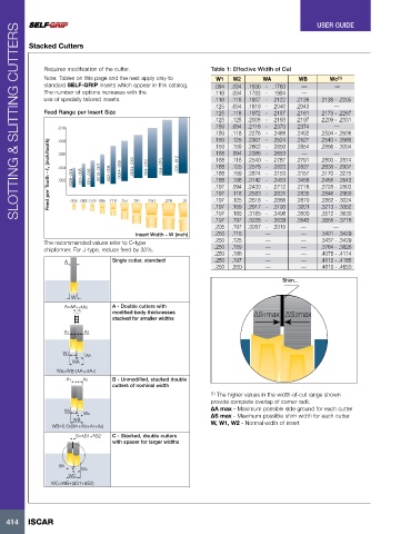
Stacked Cutters
Requires modification of the cutter. Table 1: Effective Width of Cut
Note: Tables on this page and the next apply only to W1 W2 WA WB Wc (1)
standard SELF-GRIP inserts which appear in this catalog. .094 .094 .1630 - .1763 — —
The number of options increases with the .118 .094 .1783 - .1984 —
use of specially tailored inserts. .118 .118 .1937 - .2122 .2126 .2138 - .2205
.125 .094 .1819 - .2040 .2043 —
Feed Range per Insert Size .125 .118 .1972 - .2157 .2161 .2173 - .2267
.125 .125 .2008 - .2193 .2197 .2209 - .2331
.010 .159 .094 .2118 - .2370 .2374 —
.159 .118 .2276 - .2488 .2492 .2504 - .2606
.2307 - .2524
.2527
.159
.2540 - .2669
.125
Feed per Tooth - fz (inch/tooth) .006 .0008-.004 .001-.005 .001-.005 .0015-.007 .002-.008 .0024-.009 .0024-.010 .004-.010 .004-.010 .005-.012 .188 .118 .2540 - .2787 .2791 .2803 - .2874
.008
.2866 - .3004
.159
.2602 - .2850
.2854
.159
—
—
.188
.094
.2386 - .2653
.2827
.2838 - .2937
.2578 - .2823
.188
.125
.004
.188
.3157
.159
.2874 - .3153
.3170 - .3275
.3142 - .3453
.3468 - .3543
.188
.3456
.188
.002
.197
.2716
.2728 - .2803
.094
.2430 - .2712
.118
.197
.2835
.2583 - .2831
.2846 - .2960
.197
.157
.005 .063 .079 .095 .118
.276
.197
.250
.315
.2917 - .3193
.159
.3201
.197
.3213 - .3362
.188
.197 .125 .2618 - .2866 .2870 .2882 - .3024
.3185 - .3496
.3512 - .3630
.3500
.197 .197 .3228 - .3539 .3543 .3555 - .3716
.205 .197 .3267 - .3315 — —
Insert Width - W (inch) .250 .118 — — .3401 - .3429
The recommended values refer to C-type .250 .125 — — .3437 - .3429
—
—
chipformer. For J-type, reduce feed by 30%. .250 .159 .3764 - .3826
.250 .188 — — .4076 - .4114
A Single cutter, standard .250 .197 — — .4110 - .4185
.250 .250 — — .4610 - .4650
Shim...
W
A=ΔA 1+ΔA2 A - Double cutters with
modified body thicknesses ∆S1max ∆S 2max
stacked for smaller widths
A1 A2
W1
W2
WA
WA=WB-(ΔA 1 +ΔA 2)
A1 A2 B - Unmodified, stacked double
cutters of nominal width
(1) The higher values in the width-of-cut range shown
provide complete overlap of corner radii.
∆A max - Maximum possible side ground for each cutter
W1
W2 ∆S max - Maximum possible shim width for each cutter
WB W, W1, W2 - Normal width of insert
WB=0.5x(W1+W2+A1+A2)
S=ΔS1+ΔS2 C - Stacked, double cutters
with spacer for larger widths
W1
W2
WC
WC=WB+(ΔS1+ΔS2)
414 ISCAR