
Page 125 - Aluminum_Machining_catalog_2023
P. 125
USER GUIDE
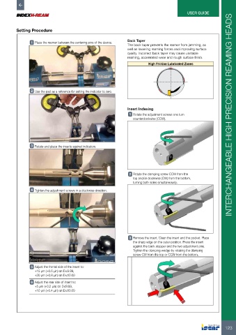
Setting Procedure
Back Taper
1 Place the reamer between the centering pins of the device.
The back taper prevents the reamer from jamming, as
well as lowering reaming forces and improving surface
quality. Incorrect back taper may cause unstable
reaming, accelerated wear and rough surface finish.
High Friction Lubricated Zones
2 Use the pad as a reference for setting the indicator to zero.
Insert Indexing
1 Rotate the adjustment screws one turn INTERCHANGEABLE HIGH PRECISION REAMING HEADS
counterclockwise (CCW).
3 Rotate and place the inserts against indicators.
2 Rotate the clamping screw CCW from the
top and/or clockwise (CW) from the bottom,
turning both sides simultaneously.
4 Tighten the adjustment screws in a clockwise direction.
3 Remove the insert. Clean the insert and the pocket. Place
the sharp edge on the outer position. Press the insert
against the back stopper and the two adjustment pins.
Tighten the clamping wedge by rotating the clamping
screw CW from the top or CCW from the bottom.
5 Adjust the frontal side of the insert to:
+15 µm (+0.6 µin) on D≤9.99,
+20 µm (+0.8 µin) on D≤10.00
6 Adjust the rear side of insert to:
+5 µm (+0.2 µin) on D≤9.99,
+10 µm (+0.4 µin) on D≤10.00
123