
Page 116 - Aluminum_Machining_catalog_2023
P. 116
USER GUIDE
INDEXABLE DRILLING INSERT
Setup of Non-Rotating Drills
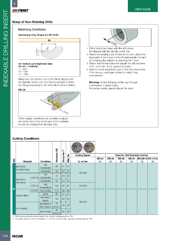
Machining Conditions
Optimizing Chip Shape for DR Drills
AL
L CORE
H2 1 Drill a hole 6 mm deep with the drill center
line aligned with the spindle center line.
2 Check the existing core. If there is no core, check the
H1
alignment of the Y-axis of the drill and spindle. Correct
by checking the adapter or adjusting the Y-axis.
for medium up to high feed rates 3 Check that the hole diameter equals the drill diameter
for iso – n material +0.0- +0.2 mm. If not, adjust the X-axis.
L – open 4 Note: In some operations, part of the core may break.
H2 – high If this occurs, use finger contact to verify if any
H1 – deep
core remains
Make Sure the Center Line of the Drill Is Aligned with
the Spindle Center Line. It Is Recommended to Verify Warning: As the drill goes all the way through
the Setup According to the Instructions Shown Below. a workpiece, it ejects a disc.
For worker safety, guards should be used.
DR-06 D-0.3 (mm)
D+1 (mm)
Under regular conditions it is possible to adjust
the center line of the drill (X-axis of the machine)
in order to change hole diameter size.
Cutting Conditions
Hardness HB Group No. (1) Cutting Speed Feed Vs. Drill Diameter mm/rev
ISO Material Condition Mat. No. Vc m/min DR-04 DR-05 DR-06 DR-07 DR-09/10 DR-11/12
AL
AL
AL
AL
AL
AL
not
aluminum- hardenable 60 21 21
wrought alloys
hardenable 100 22 22 150-300
not
≤12% Si hardenable 75 23 23
aluminum-
cast alloys hardenable 90 24 24
high
>12% Si 130 25 25 120-250
N temperature 0.08-0.24 0.12-0.25 0.12-0.25 0.12-0.25 0.20-0.30 0.2-0.35
>1% Pb free cutting 110 26 26
brass 90 27 27
copper alloys
electrolytic 100 28 28
copper
duroplastics, 70 29 29 150-300
fiber plastics shore D
non metallic 55
hard rubber 30 30
shore D
• When using external coolant supply only, reduce cutting speed by 10%
• This table refers to 2/3xD drill lengths • For 4xD and 5XD drills, decrease cutting data by 15%
114 ISCAR