
Page 75 - HOLE MAKING CATALOG p001-148
P. 75
USER GUIDE
ISO
D=4-4.9Material Groups
D=5-5.9
D=6-7.9Material
D=8-9.9
D=10-11.9
D=12-13.9
D=14-15.9
D=16-19.9
D=20-25.9
D=26-32.9
INDEXABLE DRILLS
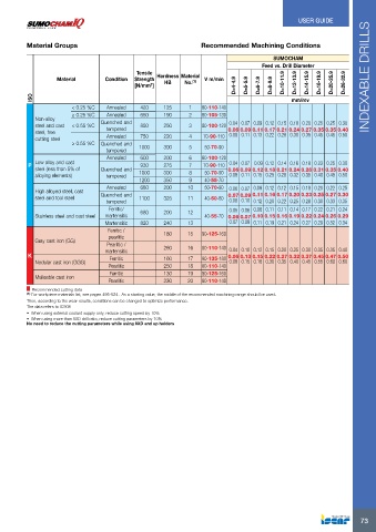
Recommended Machining Conditions
SUMOCHAM
Feed vs. Drill Diameter
Condition Tensile Hardness Material V m/min
Strength HB No.(1)
[N/mm2]
mm/rev
< 0.25 %C Annealed 420 125 1 80-110-140
≥ 0.25 %C Annealed 650 190
Non-alloy < 0.55 %C Quenched and 2 80-105-130
steel and cast tempered 850 250
steel, free ≥ 0.55 %C Annealed 3 80-100-120 0.04 0.07 0.09 0.12 0.15 0.18 0.20 0.25 0.25 0.30
cutting steel Quenched and 750 220 0.06 0.09 0.11 0.17 0.21 0.24 0.27 0.35 0.35 0.40
tempered 4 70-90-110 0.08 0.11 0.13 0.22 0.28 0.30 0.35 0.45 0.45 0.50
Annealed 1000 300
5 50-70-90
Quenched and 600 200
Low alloy and cast tempered 930 275 6 80-100-120 0.04 0.07 0.09 0.12 0.14 0.16 0.18 0.23 0.25 0.30
steel (less than 5% of 1000 300 0.06 0.09 0.12 0.18 0.21 0.24 0.26 0.31 0.35 0.40
P 1200 350 7 70-90-110 0.08 0.11 0.15 0.25 0.28 0.32 0.35 0.40 0.45 0.50
680 200 8 50-70-90
alloying elements)
1100 325 9 40-55-70
High alloyed steel, cast Annealed 680 200 10 50-70-90 0.06 0.07 0.09 0.12 0.12 0.15 0.18 0.20 0.22 0.25
steel and tool steel 0.07 0.09 0.11 0.16 0.17 0.20 0.23 0.25 0.27 0.30
Quenched and 820 240 11 40-60-80 0.08 0.10 0.12 0.20 0.22 0.25 0.28 0.30 0.33 0.35
Stainless steel and cast steel tempered
180 12 0.05 0.06 0.08 0.11 0.11 0.14 0.17 0.22 0.21 0.24
Gray cast iron (GG) Ferritic/ 40-55-70 0.06 0.07 0.10 0.15 0.16 0.19 0.22 0.24 0.26 0.29
K martensitic 260 13 0.07 0.08 0.11 0.19 0.21 0.24 0.27 0.29 0.32 0.34
Nodular cast iron (GGG) Martensitic 160 15 90-125-160
Malleable cast iron 250
Ferritic / 130 16 80-110-140 0.04 0.10 0.12 0.15 0.20 0.25 0.30 0.35 0.35 0.40
pearlitic 230
17 90-135-180 0.06 0.13 0.15 0.22 0.27 0.32 0.37 0.45 0.47 0.50
Pearlitic / 18 80-110-140 0.08 0.15 0.18 0.30 0.35 0.40 0.45 0.55 0.60 0.60
martensitic
19 90-125-160
Ferritic
20 80-110-140
Pearlitic
Ferritic
Pearlitic
Recommended cutting data
(1) For workpiece materials list, see pages 495-524 . As a starting value, the middle of the recommended machining range should be used.
Then, according to the wear results, conditions can be changed to optimize performance.
The data refers to IC908
• When using external coolant supply only, reduce cutting speed by 10%
• When using more than 5XD drill ratio, reduce cutting parameters by 10%
No need to reduce the cutting parameters while using 8XD and up holders
73