
Page 21 - Turning_catalog_INCH_2022_45_P261-508
P. 21
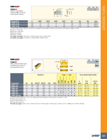
TGHN-S                                                OHN-OHX     CWN-CWX
             Single-Ended Blades
             Carrying Utility Inserts for                                       HF  H
             Grooving and Turning
                                                                  OAL      WB                                            GROOVE-TURN

              Designation            H       CWN (1)  CWX (2)  OHN (3)  OHX (4)   HF       OAL       WB      Insert
                TGHN 32-3S          1.260     .118      .118     .39      .709     .976    1.902     .094    TGMF 3
              TGHN 32-5S            1.260     .197      .197     .47      .984     .976    2.126     .157   TGMF/P 5
              TGHN 32-6S            1.260     .236      .250     .63      .984     .976    2.193     .205    TGMF 6
             •  Use the drilled holes on blade for min and max overhang • Grooving depth is limited by the insert • For user guide, see pages 471-488
             (1)  Minimum cutting width
             (2)  Maximum cutting width
             (3)  Minimum overhang
             (4)  Maximum overhang
             For inserts, see pages: TGMA (282) • TGMF (full radius) (282) • TGMF/P (281)
             For holders, see pages: C#-TBU (677) • IM-TBU (688) • UBHCR/L (673)


                                                                       INSL (Ref.)

             TGMF/P                                            ±.004
             Utility Double-Ended Inserts
             for External and Internal
             Grooving and Turning                                CW              TGMF
                                                                   RE
                                                                                 TGMP

                                            Dimensions                  Tough 1   Hard      Recommended  Machining Data


                                                                     IC830  IC8250  IC808  IC20  IC20N  IC428  ap  f turn  f groove
              Designation     CW     RE  CWTOL (1)  RETOL (2)  INSL  CDX (3)              (inch)   (IPR)     (IPR)
              TGMF 302         .118   .008   .0020   .0020   .531   .413  •  •  •  •  •  •   .010-.071   .0055-.0071   .0027-.0043
              TGMF 304         .118   .016   .0020   .0020   .533   .406  •  •  •  •  •  •   .020-.071   .0063-.0079   .0027-.0047
              TGMF 402         .157   .008   .0020   .0020   .697   .579  •  •  •  •  •  •   .008-.094   .0063-.0083   .0035-.0055
              TGMF 404         .157   .016   .0020   .0020   .697   .575  •  •  •  •  •  •   .020-.094   .0071-.0094   .0035-.0059
              TGMP 506         .197   .024   .0020   .0020   .693   .591  •       •       .030-.118   .0083-.0126   .0043-.0079
              TGMF 508         .197   .031   .0020   .0020   .701   .559  •  •  •  •  •  •   .039-.118   .0091-.0138   .0043-.0083
              TGMF 635-080     .250   .031   .0020   .0020   .872   .732  •  •  •  •  •  •   .039-.150   .0098-.0173   .0055-.0106
             •  DMIN for internal application= 807" • For cutting speed recommendations and user guide, see pages 471-488
             (1)  Cutting width tolerance (+/-)
             (2)  Corner radius tolerance (+/-)
             (3)  Cutting depth maximum
             For tools, see pages: TGDR/L (279) • TGHN 26-M (378) • TGHN-D (280) • TGHN-S (281) • TGIR/L-C (377) • TGPAD (279) • TGPAD-JHP (280)


                                                                                                                      281