
Page 119 - Turning_catalog_INCH_2022_45_P509-690
P. 119
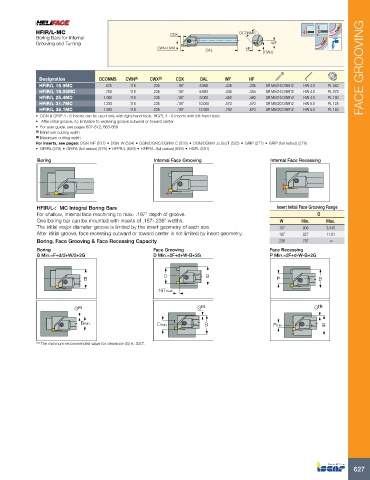
HFIR/L-MC                                   CDX                    DCONMS
               Boring Bars for Internal
             Grooving and Turning                                                          WF
                                                     CWN-CWX                      HF
                                                                     OAL                CW/2


              Designation         DCONMS   CWN (1)  CWX (2)  CDX   OAL     WF      HF                                    FACE GROOVING
              HFIR/L 15.9MC         .625    .118    .236    .197   5.906    .438    .295  SR M5X16 DIN912  HW 4.0  PL 062
              HFIR/L 19.05MC        .750    .118    .236    .197   6.693    .438    .354  SR M5X16 DIN912  HW 4.0  PL 075
              HFIR/L 25.4MC        1.000    .118    .236    .197   8.000    .450    .460  SR M5X16 DIN912  HW 4.0  PL 100
              HFIR/L 31.7MC        1.250    .118    .236    .197   10.000   .570    .570  SR M6X20 DIN912  HW 5.0  PL 125
              HFIR/L 38.1MC        1.500    .118    .236    .197   12.000   .700    .670  SR M6X20 DIN912  HW 5.0  PL 150
             •  DGN & GRIP 4 - 6 inserts can be used only with right-hand tools, HGPL 4 - 6 inserts with left-hand tools
             •   After initial groove, no limitation to widening groove outward or toward center
             •  For user guide, see pages 607-612, 663-669
             (1)  Minimum cutting width
             (2)  Maximum cutting width
             For inserts, see pages: DGN-MF (537) • DGN-W (534) • DGN/DGNC/DGNM-C (533) • DGN/DGNM-J/JS/JT (535) • GRIP (277) • GRIP (full radius) (278)
             •  GRIPA (278) • GRIPA (full radius) (279) • HFPR/L (629) • HFPR/L (full radius) (629) • HGPL (631)
             Boring                                 Internal Face Grooving                Internal Face Recessing


             HFIR/L-:  MC Integral Boring Bars                                               Insert Initial Face Grooving Range
             For shallow, internal face machining to max. .197” depth of groove.                          D
             One boring bar can be mounted with inserts of .157-.236” widths.                 W      Min.    Max.
             The initial major diameter groove is limited by the insert geometry of each size.  .157  .906   3.543
             After initial groove, face recessing outward or toward center is not limited by insert geometry.  .197  .827  11.81
             Boring, Face Grooving & Face Recessing Capacity                                 .236    .787      ∞
             Boring                                 Face Grooving                         Face Recessing
             B Min.=F+d/2+W/2+2G                    D Min.=2F+d+W-B+2G                    P Min.=2F+d-W-B+2G


                                                       D             B
                             B                                                               P            B

                                                     .197max

                          G (1)                                   G (1)                                  G (1)

                            Bmin.                    Dmin.           B                     Pmin.            B


             (1)  The minimum recommended value for clearance (G) is .020”.


                                                                                                                      627